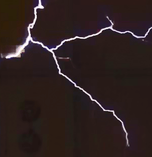
11 ft streamers
The coil needs a space
A big coil needs a big space, that has to be robust.
- There can be no electrical wiring or flammable material within the striking distance of the coil.
- The coil needs a counterpoise, a large conductive body that can absorb the energy. It could be the ground if the coil is used outdoors, or a large reinforced concrete floor inside. A non conducting floor could be covered with sheet metal in the vicinity of the coil.
- Enough mains power must be available.
My space is an underground bomb shelter that ticks most of the boxes, except that the roof is low and attracts the streamers more than I would want.
Let's have a look at the power supply components
Stockholm Tesla Coil

The power supply
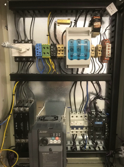
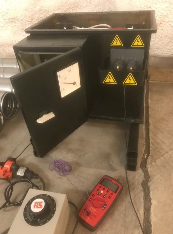
The control cabinet
This houses all the components for controlling the coil, and the ballast inductor that limits the input current to the HV transformer.
Bottom row
- Mains RFI filter
- VFD motor drive for spark gap motor
- Fuses for motor and control circuits
- Contactor for coil power
Top row
- Main power switch
- Terminal blocks
- Knife fuse holder
- Current transformer
- Overcurrent protection relay
Left side
- 63 amps socket, incoming power
Right side
- 32 amps socket, to HV transformer
- 16 amps socket, to spark gap motor
- connector for portable maneuver box
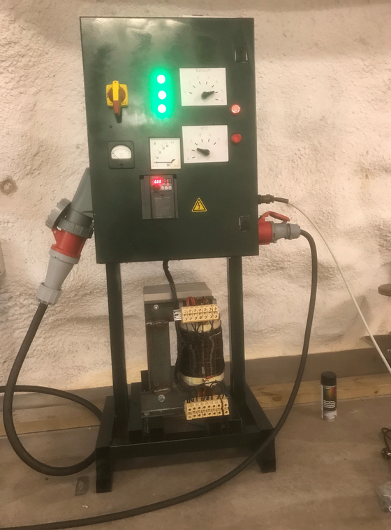
Front panel, top row
- Main switch
- Indicator LED:s, three incoming phases
- Switch, ballast taps 1-4 and off
Front panel, middle row
- Meter, voltage to HV transformer
- Meter, current to HV transformer
- Switch, extra on-off
- Indicator LED:s, power to HV transformer
Front panel, bottom
- VFD controller panel
The high voltage transformer
Home made HV-transformer
Pole pigs are preferred
Winding my own transformer was a crazy project, don´t do it if you can obtain a used "pole pig". A pig is a power distribution transformer of the kind seen on distribution line poles in rural areas, for supplying power to a small group of houses or a farm. They are used where houses are situated far apart along the power lines. They are very robust and well suited for tesla use. In my country, Sweden, they are usually 3-phase 400 V / 11 kV units, which is fine for tesla use. I would not use a transformer supplying much more voltage, as the voltages in the charging circuit will reach almost double the peak value of that voltage. At a voltage much over 30 kV it will be very difficult to prevent corona and destructive flash over, that could burn expensive coil components in an instant.
A pig can be used at about double their kVA rating for intermittent tesla use, but they should not be overvolted.
My home wound transformer
The core is made of 55 kg UI 240 core laminations, a standard size in Europe. The windings are made on a lathe, with the help of the carriage power feed for guiding the Cu-wire.
Winding specifications
- Bobbin center 80 x 100, length 240 mm, made of fiberglass laminate
- Primary, seven paralleled one layer windings, AWG 17 (1,18 mm diameter), 173 turns each
- Insulation between primary and secondary, cardboard strips and paper, 4 mm
- Secondary, 19 layers, AWG 22 (0,6 mm diameter), total of 6000 turns
- Insulation between secondary layers, 0.65 mm paper
Paper insulation under oil is very efficient and is still used today, it can withstand about 30 kV per mm if the transformer oil is dry.
The number of primary turns follows from the primary voltage and the core size. A smaller core needs more turns, and a lower voltage not so many. Too few turns will saturate the core, so that the idle current and idle losses will be too high. The idle current of my transformer is just a few amps.
Winding the secondary
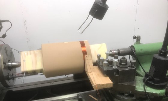
The winding starts 15 mm in from the paper ends, to create a sufficient distance to the core at both sides for good insulation. The power feed for the carriage is set to create a winding without gaps or overlaps. A photoelectric counter keeps track of the turns.
The lathe was set at it´s slowest speed, 30 rpm. The layers are alternately wound from the left and the right, the paper insulation is placed with the lathe stopped, before the carriage direction is changed.
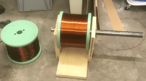
The spool of copper wire was arranged on the floor, so that the spool rotates and the wire does not kink, when it is fed on to the winding. The winding tension is controlled by hand, with the protection of a heavy leather glove.
Any jerk must be controlled by a tensioned slack each time the lathe is started. Tension must be kept on the wire at all times, when the lathe is stopped for placing the paper insulation, or for changing the carriage movement direction.
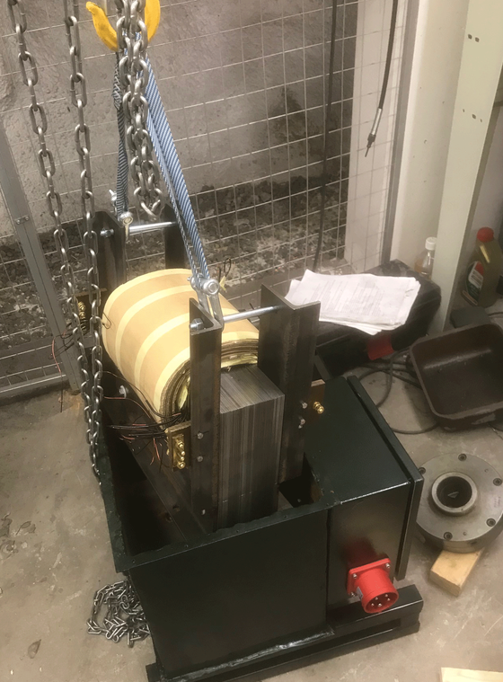
The ballast
The ballast inductor is very important. It must be regarded as an integral part of the charging circuit design for the coil. The core must have an air gap and be large enough to never be saturated.
I used 110 kg of UI 240 core laminations, without any I-laminations at all for a very large air gap (the I-laminations were removed after the picture of the control cabinet was taken). The winding bobbin is placed on one of the U-legs, it´s center for the core leg is 80 x 200 mm, the length is 240 mm.
It is myth among coilers that the ballast inductance can be calculated for a short circuit current coresponding to the coil current draw wanted. This is not the case, it must be calculated by simulation or established by experiments and measurement, more on this at the coil component page.
In retrospect the winding was overdesigned by about a factor four, for the reason mentioned, and because the very large core I used had much lower reluctance than I had expected. So I had to remove the I-laminations completely and use fewer winding taps for the correct inductance value.
It is not posible to pinpoint the inductance at the design stage, as there are too many variables that could not be estimated with enough precision. I would recommend using other coilers ballast data as a starting point, tweaking the values to suit ones needs and then adjust the final outcome by changing the core air gap distance.
A bigger core is better
A somewhat smaller core would probably also be satisfactory, but the number of turns would then have to be higher. But as a general rule a big core with a large air gap is less likely to saturate and is therefore safer. Transformer laminations are not overly expensive, so this is not the best place to save money. The current to the HV transformer could skyrocket if the ballast core is ever saturated.
No need for power factor correction
Bad power factor, a myth?
Advice concerning power factor correction for tesla coils were once abundant, but some coilers have stated that this is not necessary. Initially I did see some current lag, before my charging circuit was optimised. But as by magic, after optimising, this was no longer the case, as can be seen in my simulation on the coil component page. The I and U zero crossing is almost simultaneous in the graph, as well as in my measurements.
My view on this is that the charging circuit is not a 50 Hz circuit, it is ruled by the bps frequency and the ballast/cap combo. And if there is a balance cap/ballast at the bps setting, there will be no current or voltage lag.
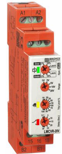
Over voltage relay Broyce LMCVR-20V
Current transformer, home made
- High permeability ferrite core
- One of the power leads passing through the toroid center
- About 30 turns AWG 17 (1,18 mm) winding
- Load resistor for the winding (very important!) 1 ohm 10 W

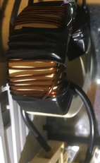
The finished transformer, before filling with oil
The transformer is mounted in the tank, and the paper insulation is dried out by applying current to the secondary from the variac, while the primary is shorted. The windings are heated to about 80 degrees celsius by this current for a few days, before the oil is filled and the tank lid is sealed.
It is very important that the paper insulation is dry, as even a small amount of water diminshes the insulation that the oil provides.
The temperature meter on the front is fed from a transducer and a thermocouple placed between primary and secondary, to indicate winding temperature. Over 100 degrees celsius is harmful for the paper insulation.
How to measure on a HV transformer
Voltage should not be applied to the primary before the unit is oil filled and sealed, as the insulation is weak without oil. Always apply voltage gradually with a variac when measuring, as the inrush current would be very large otherwise. Don´t take any measurements from the secondary as the voltage is very dangerous. It is better to measure the transformer backwards by applying voltage to the secondary, and take measurements from the primary.
The transformer tank
The transformer tank is welded from 3 mm steel. It is air tight with the lid mounted, and is vented through silica gel to absorb any moisture from outside the tank.
Ground connections
The transformer core and the tank should be connected to mains earth for safety reasons. The secondary end closest to the primary should be connected to tesla earth, so that the voltage between the primary winding and the inner secondary layer is kept low.
It is not good practice to let the secondary float without ground connection, as it could float up to any voltage and cause flash over between the windings.
Inrush current
When a large transformer is connected to the mains, the magnetic field has to be built up very quickly from zero. The inrush current could be very large, several kiloamps, especially if the core is saturated by the inrush current. That would blow every fuse in sight, and perhaps burn underdimensioned cables. The inrush current could be tamed somewhat by special NTC resistors, but better is to use a ballast before the transformer, that has such a large core that it could not be saturated. Such a ballast is very soft starting, so the variac that many coilers use to bring up the voltage gradually is unnecessary.
My view is that many coilers use underdimensioned ballasts. The core of the ballast should be at least the same weight as the transformer core, or preferably double that weight. Such a core will never saturate, the coil will be soft starting, no fuses will blow and no variac will be needed.
Ferroresonance and destroyed HV transformers
A HV transformer should never be connected to a capacitor without a properly set safety gap. A capacitor connected to an unloaded transformer will set up a very destructive chaotic resonance condition, called ferroresonance. The core will saturate and the voltage will build up to destructive levels in just a few periods of the mains frequency. The transformer will flash over internally and be destroyed, if a safety gap does not remove the energy in time.
Every tesla coil has a capacitor, so a transformer connected to a tesla coil should always have a properly set safety gap.
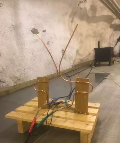
Safety gap
This is a horn gap, the 1/4 inch copper tubes are bent like two horns. When an arc fires where they are close together, the arc will then travel upwards because of the heat, until it is extinguished. The distance at the gap is adjustable, and the minimum firing voltage could be estimated as about 3 kV per mm distance.
The HV cables are RG 213 coax, with the screen connected to tesla ground.
The gap could also be used for testing the ballasted HV transformer, with a close gap setting of about 3-4 mm. This arrangement is called a "Jacob´s ladder". The gap will refire as soon as the first arc is extinguished at the top, so there will always be a climbing arc. The current will be limited by the ballast inductor, so the arrangement also tests the ballast. Without a ballast, the current would be extremely high and blow fuses, or something would be destroyed.
The ballast windings
The windings are bifilar and wound with 2 x AWG 10 (2.6 mm diameter) magnet wire. Such heavy copper wire is very stiff and has to be wound on by hand, even if the setup is on the lathe. I would not use plastic insulated wire, as the thermal transfer through the plastic is unsatisfactory.
Insulation between layers is 0.65 mm paper, and all winding taps are secured by fiberglass webbing and are extra insulated by tubing before they are brought out to the sides for connection on terminal blocks.
Total number of turns and amps when driving the coil, for each tap setting (amps at 395 V):
- Tap 1 111 turns for 27 A (17 mH)
- Tap 2 100 turns for 34 A
- Tap 3 88 turns for 43 A
- Tap 4 76 turns for 58 A (8 mH)
If I did this again I would use about 25 % less turns, keep the I-laminations and start with an air gap of about 8 mm between U- and I-laminations. The air gap could then be adjusted for the final inductance value.
The switch for the taps in the control cabinet can handle 50 amps continously, and more in intermittent tesla use. But it should not be switched live, as the large inductance of the ballast could cause heavy arcing, and in a worst case scenario destroy or even weld the switch contacts together.
Measuring the ballast inductance
It is not easy to measure the ballast inductance. The core is very unlinear at low magnetizing currents, so the inductance must be measured close to the operating current. A small signal measurement supplies no meaningful information.
I did this by measuring short circuit current with 395 V supplied to tap 1. This resulted in a current draw of 74 A, corresponding to 17 mH. By calculating backwards from the number of turns, keeping in mind that the inductance is proportional to the square of the number of turns, I arrived at the 8 mH for tap 4.
It would of course be impossible to measure the short circuit current at tap 4 directly, using the full 395 V, as the current would then be an outrageous 158 A.
And this is also the reason for other measures for controling overcurrent or short circuit incidents, these will not be limited enough by the ballast.
Over current protection
Max current and the fuses for incoming power
The fuses for incoming power, 63 A knife fuses, are not accessible to me, and I don´t want to fry those, as that could cause my land lord to ask questions I would rather not answer. So I have installed 40 A knife fuses in my control cabinet. As they are two sizes down from the 63 A fuses, they are fully selective and will always blow before the 63 A fuses. But still they will be able to provide up to 80 A for a few minutes, and that is more than I need. Knife fuses are very tolerant to moderate overload, but very fast at short circuit currents. If a real short circuit situation would occur, for example a short in the RFI filter, they would take care of that. The filter is before the ballast, so the short circuit current could be immense in case of catastrophic filter failure.
Over current relay
In case of the safety gap firing, the current would also be high, but to some extent controlled by the ballast. At the ballast setting for max coil input power, that would be about 150 A. This would take out my 40 A knife fuses after a few seconds, but I don´t want to change those every time tha gap fires.
The fix for this is a current transformer for the outgoing current, that feeds an overvoltage relay. The normally closed contact of the relay is in series with the self holding contact of the main contactor. But if the current transformer outputs more than a certain voltage, the relay contact opens and the main contactor will break the circuit. This will take a few milliseconds, but the knife fuses will hold up until the contactor does it´s job. The trip voltage for the overvoltage relay is adjustable, so the max allowed current can be set to a suitable value.
The coil could be restarted immediately after an over current incident, if that is wanted, by triggering the contactor as usual.