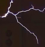
11 ft streamers
Let's have a look at the coil design
Starting point
Let´s assume a HV transformer voltage of about 12 kV, a primary cap of 200 nF and a bps (number of cap discharges per second) of 340. This would draw about 20 kW of mains power. For 10 kW about 100 nF would be required. A lower bps of 100 or 200, would need a synchronous spark gap for timing the discharges correctly, while an asynchronous gap provides more flexibility at bps rates above about 250, where the timing of individual discharges becomes less critical. At lower bps a larger cap would be needed for the same input power. At higher bps the discharges will behave almost as giant welding arcs, that tend to stick to the target for some time, while they will be more shifting and lively at lower bps.
The importance of a balanced design
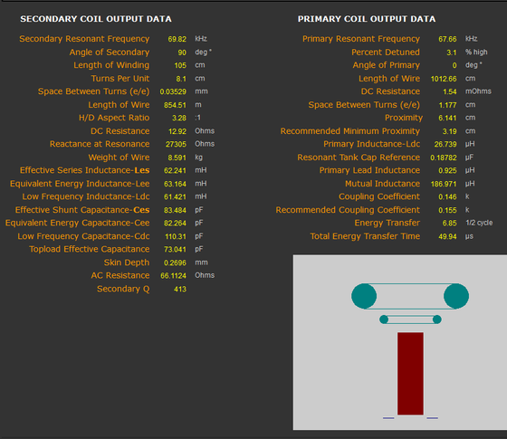
So initially the cap value should be choosen for the type of rotating spark gap and the power input wanted. When that is decided, the secondary coil dimensions should be choosen to match. A diameter of about 100 mm would be right for a 5 kW coil, while at least 300 mm would be needed for a 20 kW coil. From that point on I would recommend the use of a tesla coil design software for calculating the primary and secondary resonance frequencies, and other important data. I am only familiar with the JavaTC software, which is really good and surpringsingly precise.
Use Richard Burnett´s charging design ideas
But the charging circuit is not treated in the JavaTC software, and was poorly understood until Richard Burnett analyzed it very successfully almost 20 years ago. The charging efficiency has great influence on the power available for the streamers. A coil designed according to these principles could easily be two or three times as efficient as an arbitrary charging circuit design. This is because of energy storage and release from the ballast inductor, which enables the cap to be charged to almost double the peak voltage of the HV transformer, when the parameters are optimised. That is to about 30 kV for a 12 kV transformer.
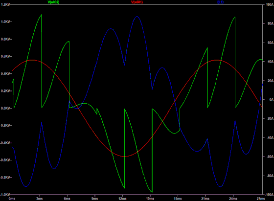
The LT Spice simulation to the right is my charging circuit, at the HV transformer primary side. The red graph is the mains voltage, the green graph is the cap voltage (refered to the primary side), with the highest peaks at almost twice the transformer input voltage. This has to be multiplied by the winding factor of 31 for about 33 kV at the cap on the secondary side. The blue graph is the charging current, and the peaks corresponds to stored and released energy in tha ballast magnetic field. Before the peak in the blue graph energy is stored, and after the peak energy is transfered to the cap, so that the cap is charged over the transformer voltage.
Richard´s website is not quite functioning anymore, but there is a mirror site, and a british coiler, Philip Tuck, has made a copy of mr Burnetts text on design theory, on his own website (that is also very good).
Manipulate a LT Spice simulation for best results
It is difficult to pinpoint the ballast inductance based just on Richard´s advice. The needed inductance will be surprisingly low for best results, in my case about a third of what would be expected based on short circuit current calculation. The charging will be near optimum when the low points of the current graph are very pronounced, as in the blue graph in my simulation.
When that is achieved, the rms current from the mains at that ballast value can be checked. In my case this is 59 A, which is near my design goal. If the current is too high, the capacitance will have to be lowered, and the ballast inductance must be raised accordingly. Or if more current is wanted, then change the other way around and check by simulations again. As long as the product of L and C is the same. the bps can also remain the same for an optimised setup.
In reality I did these changes by experiment and measurement, and did the simulations afterwards. This was a backwards way of doing it, I would have arrived at that result much faster by simulations, and then just confirming it by measurement.
My coil proportions
The JavaTC page above, is for my coil. The drawing shows how the dimensions for the primary, secondary, small and large toroid compare to each other.
LT Spice inputs
Sinus source 559 V peak (corresponding to 395 V rms) 50 Hz
Inductor 8 mH
Inductor internal resistance 0,4 ohm (corresponding to transformer and inductor copper losses)
Capacitor 200 nF
Pulse interval 3 ms (corresponding to 333 bps)
Confirmed by measuring
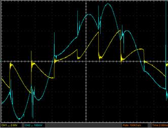
This is an actual measurement of primary current and cap voltage on my coil. The scale factor is different for the voltage, but there is a striking similarity of waveforms. And the max cap voltage is nearly identical, as well as the current rms value.
Stockholm Tesla Coil

The MMC capacitor array
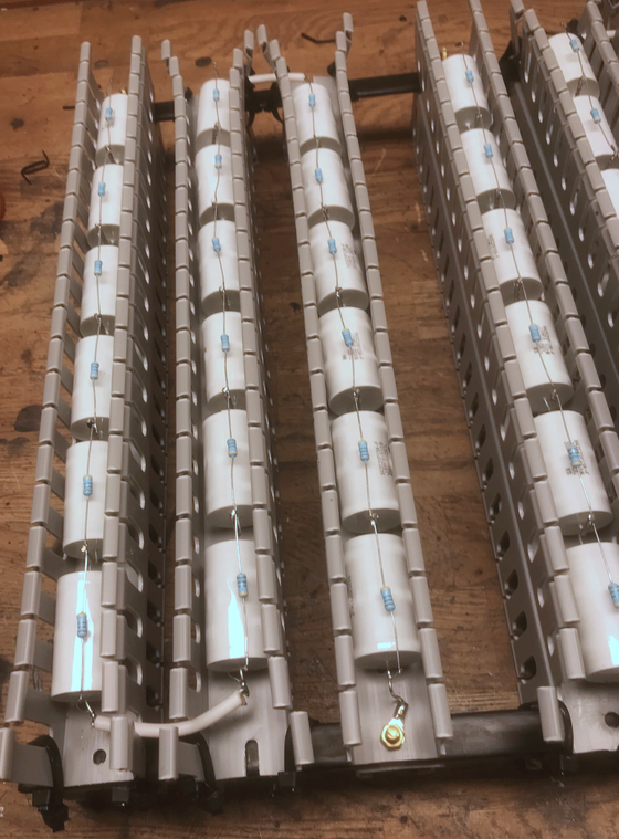
MMC - Multi Mini Capacitor
A tesla coil is very hard on the capacitor. It is charged to a very high voltage, quickly discharged at very high currents, and the repetion rate for the charging and discharging cycles is also high. The peak MMC discharge current in my coil is over 2 kA, and the repetition rate 340 times per second.
The MMC concept is designed to withstand this. It is an array of series/parallel strings of small pulse capacitors, that can handle these harsh conditions. Here is the design for my MMC-array:
Series connected capacitors in a string
- Cornel Dubilier 942C20P15K-F, 150 nF, 2000 V DC
- Strings of 18 capacitors for 36 kV DC
- Each string is "folded" three times between two copper bus bars
- The strings are held by plastic cable conduits (top part removed for the picture)
- There is a 10 Mohm high voltage metal film resistor over each capacitor, as a "bleeder" to remove the charge when not used
The strings are connected in parallel
- Each bus bar pair has four 18 capacitor strings
- The bus bars are insulated except where the capacitors are connected
- There is a distance between strings to prevent flash over
- There are six bus bar pairs for a total of 200 nF at 36 kV
The asynchronous rotating spark gap
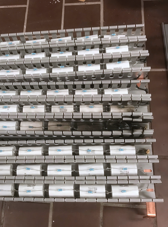
Too tight layout, flash over
Initially I had the strings arranged much closer together, and no insulation on the bus bars.
This held up before I implemented Richard Burnett´s effective charging concept. The peak voltage was probably not much over 17 kV.
But with mr Burnetts design, the voltage over the MMC rose to 32 kV. This resulted in flash over, burned plastic and burned capacitors at several locations.
More distance between rows
I had to rearrange the capacitor strings with more distance between rows, and also insulation over the bus bars and insulated leads from row to row within one string. There are sharp ends where the individual capacitor leads are twisted together, that really invites corona discharge and flash over. The distance and insulation must be sufficient to cope with that.
There are many examples of too compact layout of MMC arrays pictured on the internet, don´t be tempted to copy those. If your charging is effective, you will obtain voltages far over the transformer peak voltage, and you will experience destructive flash over in your MMC array if it is too tight.
Not every pulse capacitor is suited for tesla work
There are only a few polypropylene pulse capacitors that are known to hold up for tesla MMC use. Check out what others are successfully using, before you commit to buying a large number of capacitors for a MMC array.
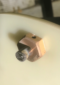
The electrodes
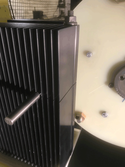
The stationary electrodes
The stationary electrodes are 1/2 inch pure tungsten bars. They are clamped in very large aluminum cooling fin blocks. The cooling blocks weigh 7 kg each. The holes for the tungsten bars are reamed to exact fit, and the cooling blocks are then slitted from from the side into the hole. The bars are clamped by a pin bolt through the slit from above, for good thermal contact.
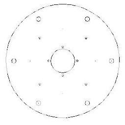
The spark gap rotor
The rotor disc is made of 10 mm FR4 fiberglass laminate. This material is extremely strong, which is important as the centrifugal forces are great at the operating speed of about 3000 rpm. The diameter of the disc is 350 mm, and there are six 16 mm holes for the brass fittings for the tungsten electrodes. Inside of these are four holes for balancing weights. The disc was water jet cut according to the cad file, to get the precision needed for good balance.
The hub
The hub was made from a standard size belt pulley, with a keyed taper lock center. The pulley was turned down in the lathe for the dimension of the FR4 disc center hole. The turning was done with the hub mounted in position on the motor shaft, for minimal run out.
Motor and balancing
The motor is a standard 1.1 kW asynchronous 2800 rpm 50 Hz 3-phase motor. The rotor with the fitted tungsten electrodes was statically balanced, mounted on the motor shaft and supported by two ball bearings. The bearings were washed clean for minimum drag. This allowed balancing to about one gram, which is satisfactory for minimizing vibration. The balancing weights are just screws in different sizes, with a varying number of washers. They are mounted in the four holes for balancing weights.
The flying electrodes
The electrodes on the rotor are mounted in center drilled M 16 brass bolts, where they are secured by set screws. The holes are reamed for a light press fit for the 3/8 inch tungsten electrodes.
For containing the flying electrodes in the unlikely case that they should ever become separated from the rotor, a piece of FR4 laminate is fastened between the cooling blocks. The speed at the perifery of the disc is over 50 m/s, so free flying electrodes would be very dangerous.
The VFD drive for the motor
The motor power is supplied from a Mitsubishi FR-D700 variable frequency drive unit in the control cabinet. The speed of the motor can be regulated up to about 4 000 rpm. The speed is usually set to about 3 400 rpm, which supplies 340 breaks per second (bps) with the six flying electrodes.
The spark gap
Spark gap distance
The distance is about 0.4 mm when the flying and stationary electrodes are closest. There are actually two gaps, one on each side of the rotor disc.
Temperature and ablation of the electrodes
The temperature of the cooling blocks and of the flying electrode brass fittings have never been above 40 degrees celsius after a few minutes of running the coil. The flying electrodes are cooled by the air flow, and the stationary electrode cooling fin blocks are very large, and can absorb and radiate a lot of heat.
Some pitting of the tungsten electrodes is visible, although the melting point for tungsten is as high as 3 540 degrees celsius.
The 3-phase motor
Grounding for the motor
The motor chassis is grounded to mains earth. The insulation between motor windings and the motor chassis can probably not stand much potential difference. The cable to the motor is screened to protect the VFD drive from radio frequency radiation from the coil. That screen is also connected to mains earth. A separate screen is applied over the cable outer insulation, and that screen is connected to tesla ground.
The idea is that the cable is protected from overvoltage from streamer strikes by the outer screen. But the motor itself, and the VFD drive, is protected by the mains ground. This can be expected to be closer to the potential of the incoming 3-phase power for the motor, and therefore to be kinder to the motor insulation.
The secondary
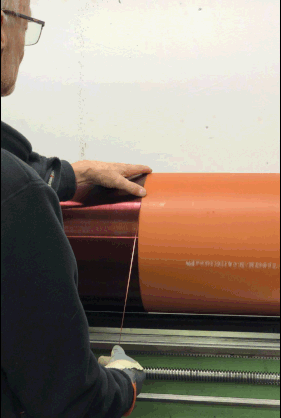
Winding the secondary
The coil form is a polypropylene sewer pipe, the diameter is 315 mm . Winding length is 1020 mm of AWG 17 (1.2 mm diameter).
The coil form is almost too big for my lathe, so it was difficult to rig and I could not use the carriage for wire feed. The copper wire was guided by hand at 30 rpm. The winding ends are secured by fiberglass straps and small polyamide screws. The threaded screw holes do not penetrate the coil form.
The coil was varnished with polyester resin, while the lathe rotated the coil form.
The polyester resin will not get a good grip on the oily surface of the polypropylene coil form, but it will bond the wire turns to each other. The polyamide scews at the winding ends will stop the coil from sliding on the form.
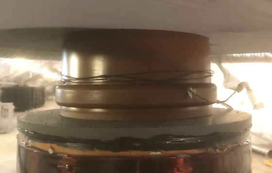
The end caps
Each end cap consists of two plastic discs, one smaller inside the coil form and one on top. These are fastned by polyamide screws, and are also caulced to the coil form around the perifery.
The secondary is held by a central 160 mm sewer pipe, that is secured to the base. There are holes in the end caps for this central holding pipe.
The primary
The primary supports
The plastic radial supports for the primary are fixed by polyamide screws to the plastic base plate. Polyamide threaded rods makes it possible to adjust the height of the primary base plate, and therefore the distance between primary and secondary. This distance determines the k-factor, the coupling coefficient between the primary and secondary coils.
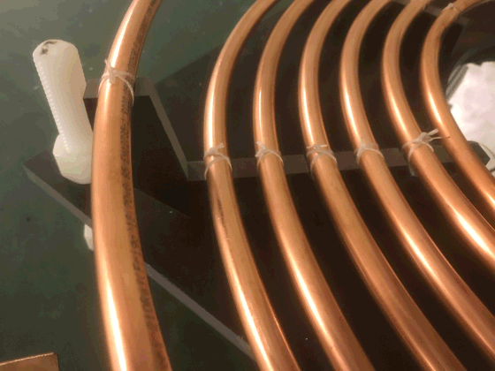
Primary coil
The six turn primary is made of 1/2 inch copper refridgeration tubing. The turns are tied to slots in the primary supports. Outside of the primary is an elevated strike ring, that is connected to tesla ground. The purpose of this is to attract streamers that would otherwise hit the primary. The strike ring is of course an open turn, to not pull any energy from the magnetic field.
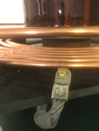
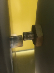
Primary coil clamp
A sliding copper clamp makes it possible to connect more or less turns. This is set at 5 and 2/3 turns. The setting is adjusted for maximum streamer length.
The cabling has to have a very large area, as the current is high. The temperature of the primary is about 30 degrees celcius after a few minutes running.
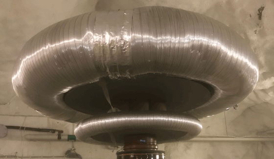
Stacked toroids
The purpose of the two stacked toroids is to form the electric field to protect the upper part of the secondary, and to direct the streamers outwards. The smaller toroid is made of 100 mm flexible aluminum ventilation duct, the larger of 315 mm duct. The outer diameter of the small toroid is 780 mm, the outside diameter of the large toroid is 1500 mm.
The importance of toroid size
The major diameter of the larger toroid will determine how much charge it will be able to hold, the smaller diameter will determine the voltage required for brake out of streamers from the surface. The general consensus is that a minor diameter about equal to the secondary diameter is a good starting point. The major diameter is more of a matter of opinion, but 1 - 1.5 times the secondary winding length is common.
Fabricating the toroid
The flexible aluminum ventilation duct is not so expensive, but it is fragile and difficult to handle without denting it. It is supported by two circular plywood boards, that are held at a distance by wooden supports. The ventilation duct is glued to the plywood by fibreglass reinforced polyester resin, "plastic padding".
I could not avoid some dents, the ugliest are covered by aluminum tape. This tape is also used to provide small brake out points on the surface, to direct the streamers. Without these, the streamers will tend to start from any imperfection on the surface.
The toroids
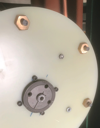
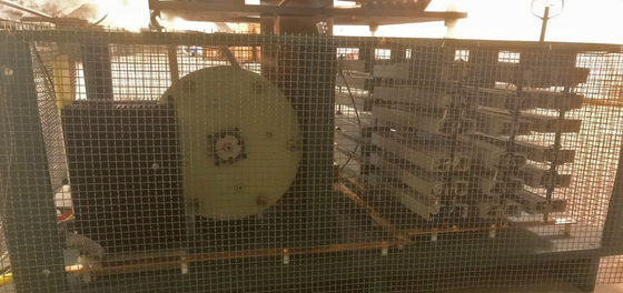
The coil base
The coil base is fabricated from plywood boards. The horizontal bus bars are made from 3 x 30 mm copper, mounted on stand off insulators. The rotating spark gap is on the left, and the MMC array on the right.
The metal screens are connected to tesla ground, and will stop streamers from hitting the primary and charging circuits.
Some final advice
To build a large spark gap coil
I have no experience in solid state coils, so I can only speak about spark gap coils.
A rotary spark gap
For a coil processing more than a few kilovoltamps, a rotary spark gap is a must. A stationary gap will overheat or not quench at all. If you plan a high bps rate, you won´t benefit much from a synchronous gap. An asynchronous rotating spark gap is easier to make.
Begin with the most difficult components
It is best to start with the components that are most difficult to obtain, or to fabricate. Until these are secured, there is no reason to spend time or money on anything else.
For most of us, the difficult components will be the HV transformer, the ballast inductor and the rotary spark gap. Make every effort to get a used pole pig, making your own transformer entails much work.
The rotary spark gap will be difficult without a lathe and some machining skills, or an interested friend with access to this. The rotary disc has to be well balanced, and that requires some precision. You might consider having the rotary disc water jet cut for best precision.
Good insulation
Don´t use wood for anything in contact with the primary circuit. Wood will arc internally, so use plastic for all insulation. Use adequate distance between HV parts, sharp ends could arc over surprising distances. If you implement Richard Burnett´s charging design, primary voltages will be far over the peak transformer voltage.
Don´t rely on one switch
Contacts in switches or contactors can get welded together by arcing, or get stuck near contact. Therefore you should open at least two sets of contacts in series, before you touch anything in the HV circuit.
Be systematic about safety
Create good routines that you always stick to, before going close to the transformer or coil. Use an insulated stick to short the transformer secondary, and short directly over the capacitor array, before touching anything. Make no exceptions from that.
Be careful about measuring on the HV transformer or ballast
Don´t measure anything on the transformer secondary. Be very careful if you connect DC for measurement on a big iron cored coil, the induced voltages when disconnecting DC could be enormous.